Skip to navigation
Skip to main content
Home
Engineering Education Products
About us
Blog
Project Documentation
0
Menu
0
0
Thermodynamics
Home
»
Thermodynamics
Showing 1–12 of 68 results
Sorted by latest
Show sidebar
Show
9
12
18
24
Sort by popularity
Sort by latest
Sort by price: low to high
Sort by price: high to low
Compare
Quick view
Add to wishlist
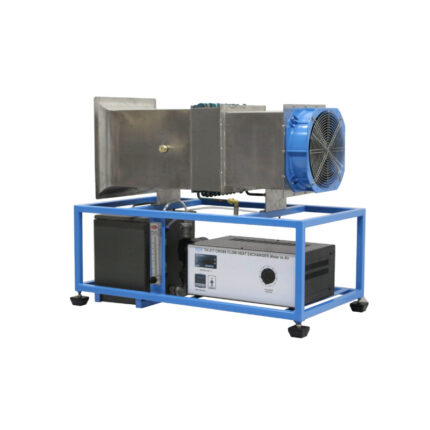
Cross Flow Heat Exchanger (Water-to-Air)
Air Flow and Thermodynamics
Compare
Quick view
Add to wishlist
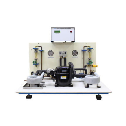
Refrigeration Trainer
Air Flow and Thermodynamics
Compare
Quick view
Add to wishlist
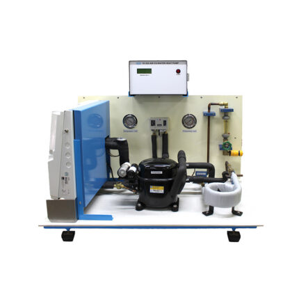
Air-To-Water Heat Pump
Air Flow and Thermodynamics
Compare
Quick view
Add to wishlist
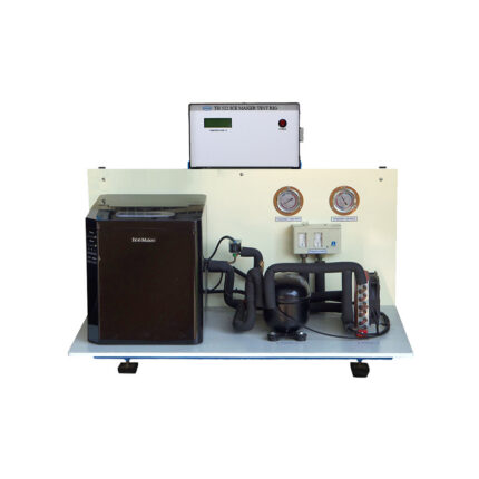
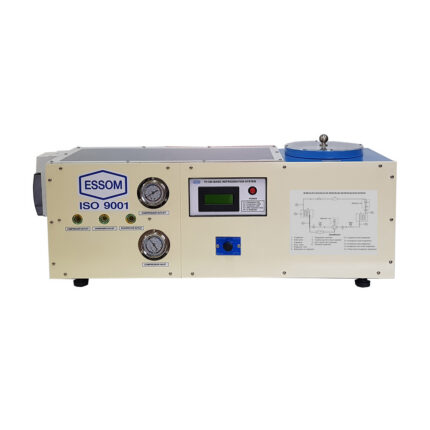
Ice Maker Test Rig
Air Flow and Thermodynamics
Compare
Quick view
Add to wishlist
Basic Refrigeration System
Air Flow and Thermodynamics
Compare
Quick view
Add to wishlist
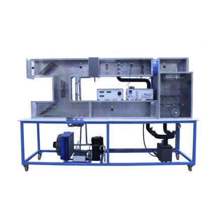
Recirculating Air Conditioning Unit (with Climatic Chamber)
Air Flow and Thermodynamics
Compare
Quick view
Add to wishlist
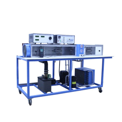
Laboratory Air Conditioning System
Air Flow and Thermodynamics
Compare
Quick view
Add to wishlist
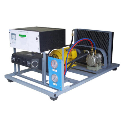
Car Air Conditioning System
Air Flow and Thermodynamics
Compare
Quick view
Add to wishlist
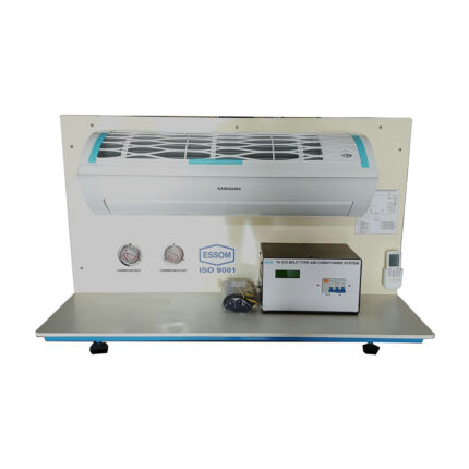
Split Type Air Conditioner System
Air Flow and Thermodynamics
Compare
Quick view
Add to wishlist
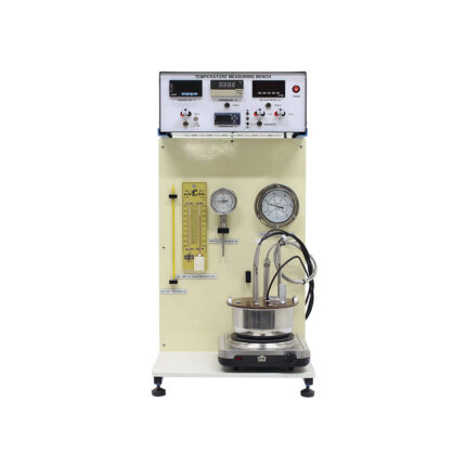
Temperature Measuring Apparatus
Air Flow and Thermodynamics
Compare
Quick view
Add to wishlist
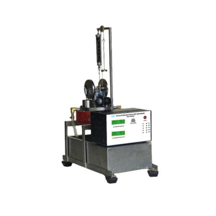
Stirling Cycle Hot Air Engine: Twin Power
Air Flow and Thermodynamics
Compare
Quick view
Add to wishlist
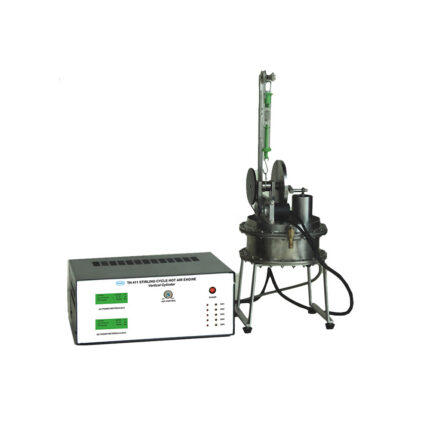
Stirling Cycle Hot Air Engine: Vertical Cylinders
Air Flow and Thermodynamics
Search
Start typing to see products you are looking for.
Search
Menu
Categories
Air Flow and Thermodynamics
Energy System & Renewable Energy
Automation
Pneumatics
Automotive
Chemical Engineering & Food Technology
Communications
Electronics, Control System and Instrumentation
Micro Controllers
Fluid Mechanics
Flow Measurement and Flow Study
Hydraulic Studies and Accessories
Pump Test Set
Turbine Test Set
Machine Elements and Theory of Machines
Marine, Naval, Hydrodinamic and Oceanograph
Mechatronics
Miscellaneous Equipment
Peripheral Devices
PLC Trainers
Process Control
Robotic Arms
Strength and Property of Materials
Structures and Accessories
Uncategorized
Home
Engineering Education Products
Blog
Projects
About us
Contact Us
Wishlist
Compare
Login / Register