• Data AcQuisition software (HR DAQ)
    Marine, Naval, Hydrodinamic and Oceanograph

    Data AcQuisition software (HR DAQ)

    The Data AcQuisition software (HR DAQ) is used to collect and analyse data from a variety of instruments used in physical models such as wave gauges, Acoustic Doppler Velocimeters (ADV) and pressure sensors.

    Product features:

    • Specifically designed for wave analysis
    • Instrument calibration
    • Data collection
    • Spectral analysis
    • Statistical and wave counting analysis
    • Reflection analysis

    Data AcQuisition software (HR DAQ)

    This comprehensive Windows based data acquisition and analysis program, suitable for 64 analogue input channels, is project based and is split into three sections.

    Calibration and scaling of inputs

    The calibration section allows the modeller to calibrate any instruments installed in physical models that require regular in-situ calibration, such as resistance type wave probes. It also allows the modeller to enter factory calibrations for other sensors such as pressure sensors.

    This section creates calibration files for use with the acquisition and analysis sections. It provides a comprehensive set of facilities for setting up the calibration files that are used to convert the analogue voltage signals in the model, to data at full scale, assuming Froude or Reynolds scaling.

    Data acquisition

    HR DAQ is set to collect raw data for a specified period of time at a specified frequency.

    Data analysis

    After the data has been collected, HR DAQ can be used to perform a number of analysis routines. The principal analysis program includes two routines; one is a Fast Fourier Transform spectral analysis and the other a statistical one.

    Specification

    Calibration routine:

    • Labelling of input channels
    • Automatic calibration with Linear Least Squares fit shown for each channel
    • Automatic setting of zero levels

    Data collection:

    • Sampling frequency 1-500Hz
    • Monitoring of channels during data collection
    • Trace of all channels displayed or turned off as necessary
    • Elapsed time and time to completion
    • Requires compatible Analogue to Digital (A/D) converter

    Data analysis:

    • Spectral analysis
    • Energy density
    • Hs m0, m2, m4, Tp

    Statistical analysis:

    H1/3, Tm, Standard deviation, Variance, Reflection analysis, Bulk reflection coefficient, Incident and reflected spectra

    Hardware/software requirements:

    • Desktop or laptop with Quad Core processor
    • Software can be downloaded directly from our web-server
    • Windows-based environment operating system
    • One user licence activation code provided per computer
    (0 reviews)
  • Robotics (SCARA) rexroth by bosch
    Automation

    Robotics (SCARA)

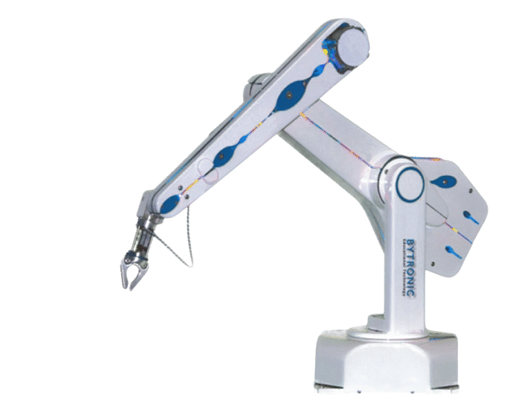
    This system consists of a single station with complete protective housing, which secures the pivot range of the robot. The station is mechanically connected to the modular mechatronics system (mMS4.0).
    The dimensions of the individual stations are smaller than 1350 x 1350 x 1900 (L x W x H). In order to ensure easy transport, the system consists of two individual stations which may not be wider than 675 mm (standard door, lift, vehicle).

    The entire system has a maximum weight of 300 kg. The supply voltage is 230 V single-phase. All protective doors and the cell are equipped with safety technology. A safety circuit monitors the system.

    The robot is operated with a handheld control panel with 3.8” display. The robot is designed as a 4-axis system (X-Y-Z axes, pivoting Z axis). The robot’s Z axis has a stroke of 400 mm and can execute 360° screwing movements. The robot is equipped with a pneumatic gripper.

    The load capacity is 5 kg, repetition accuracy for positioning is +/- 0.02 mm for the X/Y/Z axes and +/- 0.03 degrees for the rotary axis. The system is programmed with an IEC 61131-3 PLC. The robot’s motions are fully programmable via the PLC. The whole system is completely assembled and delivered in fully functioning condition.

    The PLC (industry standard) control provides some specific possibilities:
    ▶▶ PLC programming according to IEC61131-3: with the languages Instruction List, Ladder Diagram, Function Block Diagram, Sequential Function Chart, Structured Text.

    Industry 4.0:
    OpenCore Engineering enables direct reading of data from the PLC using high-level language programming, even parallel to a running PLC program (conversion of Big Data). An app is available to diagnose the PLC. The communication between the PLC and the robotic control takes place via PROFINET.

    The following practice topics are addressed:
    ▶▶ Description of individual components and commissioning of a robotic system
    ▶▶ Basic knowledge to create programs; control types
    ▶▶ Creation of programs in a PLC programming environment (IEC 61131-3)
    ▶▶ Programming individual movements and motion sequences
    ▶▶ Gripping and positioning cube-shaped housings
    ▶▶ Teaching program points
    ▶▶ Programming the HMI to operate the robot via PLC

    The exercises are available online.
    Exercises with solutions are available to the trainer.

    The work station includes:
    ▶▶ 4-axis swivel-arm robot
    ▶▶ Robot control with a PLC according to IEC61131-3
    ▶▶ Safety relay
    ▶▶ HMI for robot operation via PLC
    ▶▶ Housing cube, aluminum
    ▶▶ Housing cube, plastic, black
    ▶▶ Pins (for connecting the housing cubes)
    ▶▶ Pneumatic maintenance unit
    ▶▶ Pre-wired switch box
    ▶▶ Protective housing

    The swivel-arm robot meets industry standards. So that students can recognize it in their future work, it is a robot that is used in real-world automation applications.

    (0 reviews)
  • Rexroth by Bosch - Collaborating Robot - APAS
    Automation

    Collaborating Robot – APAS

    This collaborating robot meets industry standards. The system is an individual station consisting of a robot with a capacitive outer skin, which secures the entire pivot range of the robot and enables human interaction. The entire system is fully assembled and fully functional on delivery.

    ▶▶ Safety certification through the trade association (Berufsgenossenschaft [BG])
    ▶▶ Sensor skin (capacitive), which reliably prevents collisions in the range of the robot arm
    ▶▶ Touchless collision protection with stop and automatic process continuation starting at the last position
    ▶▶ Retracting gripper fingers, which reliably prevent pinching injury in the direction of the finger axes
    ▶▶ Pinch protection with safe limiting of the clamping force of the gripper fingers
    ▶▶ Three-finger universal gripper, force and position controlled, with crush protection
    ▶▶ Securing of parts in the universal gripper in the event of power outage
    ▶▶ Camera head with:
    ▶▶ three high-resolution cameras, two of which are stereo cameras
    ▶▶ integrated LED-infrared-flash
    ▶▶ an additional LED projector for 3D photography of the handling components
    ▶▶ Operating software with:
    ▶▶ graphic representation of work plans
    ▶▶ dialog-oriented creation and parameterization of work plans
    ▶▶ dialog-led teaching of characteristics for 2D and 3D image processing
    ▶▶ three password-protected user levels
    ▶▶ extensive diagnostic options
    ▶▶ Touchpad control panel with E-Stop
    ▶▶ Remote interface (when permitted by the network connection)
    ▶▶ Mobile, portable and stable basic housing
    ▶▶ Four rollers, easily lockable with thumb screws
    ▶▶ Sturdy full-wrap handle
    ▶▶ Electric switch cabinet, integrated into the basic housing, for robotic control, control computer, safety PLC and electric
    network connection. Easily accessible via removable service covers.
    ▶▶ 16 digital inputs and outputs, 24 V optocoupled
    ▶▶ Self-adhesive labeling for reference
    ▶▶ 5 m power cable for 230 V supply voltage, Ethernet and digital I/O, built-in and lockable machine connector, heat exchanger with CEE network plug, RJ45 and Sub-D plugs

    The following practice topics are addressed:
    ▶▶ Description of individual components, commissioning of a robotic system and first movements
    ▶▶ Basic knowledge to create programs
    ▶▶ Teaching of program points
    ▶▶ Creation of programs with the touchpad control panel
    ▶▶ Integration of the camera system

    The exercises are available online.
    Exercises with solutions are available to the trainer.

    This work station includes:
    ▶▶ An operational robot system with sensor skin (capacitive), touchpad control panel, three-finger universal gripper, camera head and robot control

    (0 reviews)
  • Rexroth - Station 3 - mMS4.0 (High Rack Storage)
    Automation

    Station 3 – mMS4.0 (High Rack Storage)

    For the mechatronics learning topics (Basic to Professional), real production equipment, a mechatronics system, is provided, which consists of 3 stations. All 3 work stations can be used individually or be connected to form a larger system. The work stations described here are made of industrial components (industry standard).

    The stations have interfaces (compressed air, power, data, Ethernet) to connect more stations. For connected stations, the emergency stop for each individual station is effective for the entire connected system. The individual stations are fully installed and fully functional on delivery.

    The modular mechatronics system (mMS4.0) features the assembly of a cube-shaped housing. Thus, 2 housing cubes are prepared, connected to each other or fit together and stored. In order to provide various product types, a different color is used for each housing cube.

    This station features a storage system. The finished housings are placed in a high rack storage system by a cartesian robot with a pneumatic gripper (4-axis system).

    Notes for Station 3:
    Station 3 “high rack storage” can be converted to a CNC system. This is possible without any change to the control hardware, but only by switching the firmware (different flash card).

    Station 3 has its own control (IndraLogic L45).
    The (industry-standard) control offers several specific possibilities:
    1. PLC programming according to IEC61131-3 with the languages Instruction List, Ladder Diagram, Function Block Diagram, Sequential Function Chart, Structured Text
    2. Convertible into a CNC control via Flash card (Station 3)
    3. As preparation for Industry 4.0 (i4.0) learning topics: the control can be accessed with other programming languages (e.g. VisualBasic, C++, C#, Java, …) using OpenCore Engineering and control via a software program (e.g. LabView, MatLab/Simulink, Excel, Power Point,…) is possible. This is possible without PLC programming. By using high-level language programming it is possible to read data directly from the PLC, even parallel to a running PLC program (conversion of Big Data). Example of an i4.0 application that is possible with the control described above: direct control of a system with a LabView program (from the appropriate LabView lab) via the control, without needing to translate into a PLC programming language.

    The following practice topics are addressed:
    ▶▶ Getting to know the system and PLC program
    ▶▶ Understanding the emergency stop circuit
    ▶▶ Commissioning of electric servo axes
    ▶▶ Monitoring and control of drive controllers with PLC
    ▶▶ Connecting power
    ▶▶ Moving to a specific point
    ▶▶ Loading and storing a workpiece (cartesian robot)
    ▶▶ PLC programming according to IEC 61131-3

    The exercises are available online.
    Exercises with solutions are available to the trainer.

    The work station is equipped with the following components:
    ▶▶ Setup on an 800 x 550 mm aluminum profile plate
    ▶▶ Base: profile carriage 800 x 800 x 1350 mm (L x W x H) with electrically pre-wired control box, with the following and other components:
    ▶▶ IndraLogic L45 PLC, IEC 61131-3 compatible, convertible to CNC (see description above)
    ▶▶ Safety relay for emergency stop circuit
    ▶▶ Energy supply for 24V power supply
    ▶▶ Industrial machine control desk with quick-connect for grooved panel/perforated panel
    ▶▶ Maintenance unit for compressed air
    ▶▶ Conveyor with 24 V DC motor w/ 800m length to achieve transfer to next station with same conveyor
    ▶▶ High rack storage with at least 3 x 5 positions
    ▶▶ Cartesian robot for placement on high rack storage system, consisting of 2 electric servo axes, one pneumatic gripper, one pneumatic rotary axis and a pneumatic axis for moving the gripper to the conveyor or into the storage area
    ▶▶ Protective housing with door made of aluminum profile and plexiglass for Station 3. The door must be equipped with a safety latch
    ▶▶ Decentralized fieldline I/O, connection of system components with PLC via cable with M8 plugs
    ▶▶ Housing cubes made of aluminum, PVC (white) and PVC (black)
    ▶▶ IndraWorks programming software (one license)
    ▶▶ Documentation CD (operating instructions, operating diagrams, etc.)
    ▶▶ Ethernet switch for other needed network participants, e.g. PC, route, RFID etc

    (0 reviews)

BLOG NEWS