


Bed Profiling System
Bed profiling system is the result of much development work by HR Wallingford to meet the exacting requirements of hydraulic modellers and to ensure a high degree of reliability.
Bed Profiling System
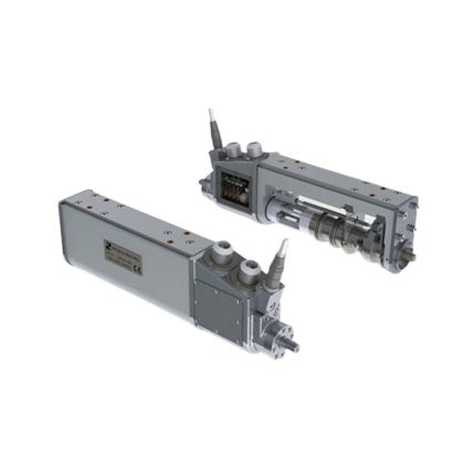
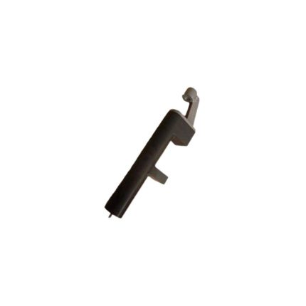
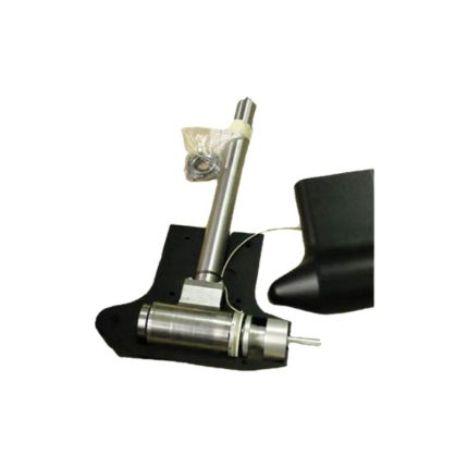
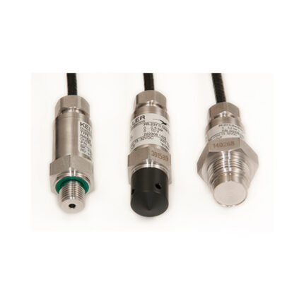
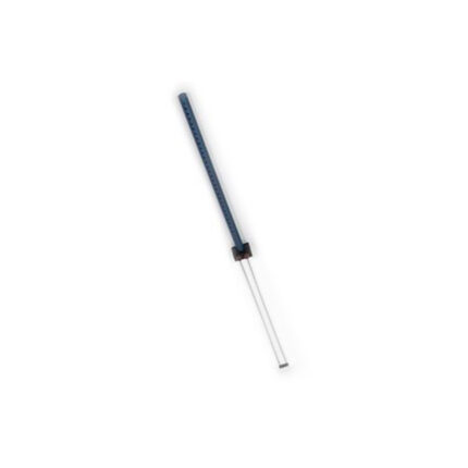
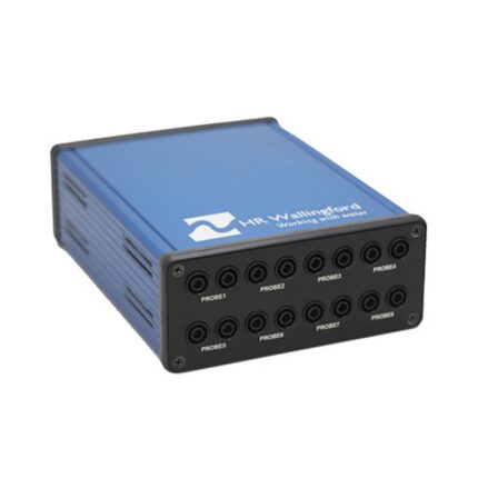
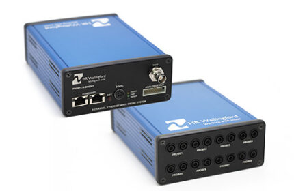
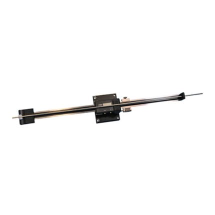
Our bed profiling system is used to assess the effect flowing water has on mobile sediment beds. It is available with a choice of probes to suit a wide range of applications.
Our bed profiling system is the result of much development work by HR Wallingford to meet the exacting requirements of hydraulic modellers and to ensure a high degree of reliability.
It utilises our traverse system to position the profiler in a 2D or 3D environment.
Bed Profiling System
| Max beam spans | 6 m (x-axis) and 6 m (y-axis) |
| Horizontal travel | Beam length less 200 mm (to allow for carriage and end stops) |
| Beam deflection | 0.5 mm with 4 m support centres |
| Horizontal velocity | Up to 50 mm/s |
| Vertical velocity | Up to 25 mm/s |
| Horizontal resolution | ±0.5 mm |
| Vertical resolution | ±0.5 mm |
| Touch probe: bed contact pressure | 10g over 20 mm diameter |
| Laser probe: maintained height above bed | 80 mm |
| Vertical travel | 1 m |
| Power supply | 220 or 110V AC |
| Standard cable length | 25 m |
Product features
- Ulises our traverse system to position the profiler in a 2D or 3D environment
- Operates both with and without water present
- Choice of laser or touch-sensitive probes
- Accuracy of ±0.5mm vertically and horizontally
- Positive non-slip drives
- Data stored in ASCII format
- Easy to install
Instrument Traverse System
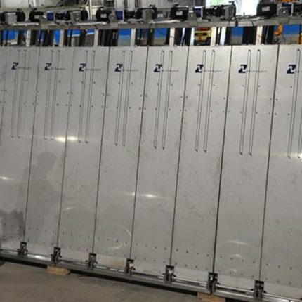
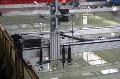
Our instrument traverse system is used to move a range of physical modelling instrumentation to a variety of different positions within a flume or basin in either two or three dimensions.
The instruments are secured to the vertical axis of the system, using a variety of fixings. The vertical axis is attached to a carriage which moves along a fixed horizontal beam to allow positioning of the instruments anywhere within the flume or basin. The traverser can be controlled by a software application that logs the exact time-stamped position of the instruments to an accuracy of ±0.5mm in both vertical and horizontal axes. A stepper motor with an integral encoder is used to drive each axis into position along the carriage using a toothed belt arrangement.
Our Instrument Traverse Systems are individually designed for each application. See Specification for an example of a typical specification.
Instrument Traverse System – Example of Specification
| Horizontal beam (x-axis) | |
| Maximum overall length | 6 m |
| Maximum travel | 5.8 m |
| Maximum velocity | 50 mm/s |
| Positional accuracy | ±0.5 mm |
| Horizontal beam (y-axis) | |
| Overall length | 4 m (dual motors required for lengths >2.0m) |
| Travel | 3.8 m |
| Maximum velocity | 50 mm/s |
| Positional accuracy | ±0.5 mm |
| Vertical beam (z-axis) | |
| Travel | 0.6 m or 1.2 m |
| Maximum velocity | 25 mm/s |
| Positional accuracy | ±0.5 mm |
| Lifted weight of instruments | 5 kg |
| Supply voltage | 220V AC or 110V AC |
| Brand | HR Wallingford |
|---|