Automation
Showing 19–22 of 22 results
-
 Automation
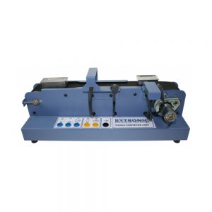
Single Conveyor Unit
The Single Conveyor Unit (SCU) has been designed as a representation of a conveyor system used in the manufacturing process to allow the study of control methods used at an introductory level. The unit is based around a common application found in industry of sorting items as they travel along a conveyor system.
The unit consists of a belt conveyor driven by a 24V d.c motor with sensors and an actuator situated along its length. Two different sized metal boxes are placed in turn at the start of the conveyor and as the box travels along the conveyor it enters an area consisting of two sensors that determines the length of the box. At the end of the conveyor is a sorting area with a sensor and linear solenoid. In the sorting area, the sensor detects the box and through the program controlling the single conveyor, the box is either accepted and allowed to continue or rejected, and ejected by the solenoid.
Connection to a PLC is through two 24V d.c D type connectors and 24V d.c 4mm colour coded shrouded sockets. The PC can be connected using a suitable interface card connected to a 26-way IDC connector with TTL.
Experiments:
- Belt conveyor control
- Rejecting A Box
- Sorting boxes
- Time-out error detection
Key Features
- Introductory level to PLC or PC control programming
- Representation of a single automated conveyor system
- Fundamental study of sensors, actuators and motors
- Component detection rejection and acceptance
- Connection through D type, IDC and 4mm connectors
(0 reviews) -
 Mechatronics
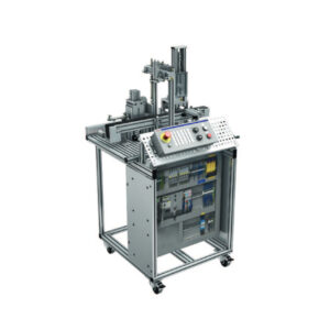
Station 1 – mMS4.0 (Material Transport and Detection)
For the mechatronics learning topics (Basic to Professional), real production equipment, a mechatronics system, is provided, which consists of 3 stations. All 3 work stations can be used individually or be connected to form a larger system. The work stations described here are made of industrial components (industry standard).
The stations have interfaces (compressed air, power, data,
Ethernet) to connect more stations.For connected stations, the emergency stop for each individual station is effective for the entire connected system. The individual stations are fully installed and fully functional on delivery.
The modular mechatronics system (mMS4.0) features the assembly of a cube-shaped housing. The 2 housing cubes are prepared, connected to each other or joined together and stored. In order to provide various product types, a different color is used for each housing cube.
At Station 1, the housing cubes are available on a conveyor. Using different sensors, position and color (light/dark) are detected and the housing cubes are forwarded or rejected. To wire the system components, a Profibus coupler is used on the grooved panel, to which the component cables are clamped. In addition, it is connected to the control with a Profibus cable.
Station 1 has its own control (IndraLogic L25).
The (industry-standard) control offers several specific possibilities:
1. PLC programming according to IEC61131-3 with the languages Instruction List, Ladder Diagram, Function Block Diagram, Sequential Function Chart, Structured Text.
2. Convertible into a CNC control via Flash card (Station 3)
3. As preparation for Industry 4.0 (i4.0) learning topics: the control can be accessed with other programming languages (e.g. Visual-Basic, C++, C#, Java, …) using OpenCore Engineering and control via a software program (e.g. LabView, MatLab/Simulink, Excel, Power Point,…) is possible. This is possible without PLC programming.By using high-level language programming it is possible to read data directly from the PLC, even parallel to a running PLC program (conversion of Big Data). Example of an i4.0 application that is possible with the control described above: direct control of a system with a LabView program (from the appropriate LabView lab) via the control, without needing to translate into a PLC programming language.
The following practice topics are addressed:
▶▶ Getting to know the system and PLC program
▶▶ Understanding the emergency stop circuit
▶▶ Detecting material with sensors
▶▶ Visualizing and operating equipment functions
▶▶ Visualizing system conditions
▶▶ Single-step and automatic modes
▶▶ PLC programming according to IEC 61131-3The exercises are available online.
Exercises with solutions are available to the trainer.The work station is equipped with the following components:
▶ Setup on an 800 x 550 mm aluminum profile plate
▶ Base: profile carriage 800 x 800 x 1350 mm (L x W x H) with electrically pre-wired
▶ IndraLogic L25 PLC, IEC 61131-3 compatible (see page 216 for description)
▶ Safety relay for emergency stop circuit
▶ Energy supply for 24V power supply
▶ Industrial machine control desk with quick-connect for grooved panel/perforated p
▶ Maintenance unit for compressed air
▶ Conveyor with 24 V DC motor w/ 800m length to achieve transfer to next station wi
▶ Separator magazine for the housing cubes. These are pushed to the conveyor via a
▶ Sensor, reed contact, pneumatic cylinder in out or in position
▶ Sensor, roller, housing detection in magazine
▶ Sensor, capacitive, housing on conveyor
▶ Sensor, inductive, metallic housing
▶ Sensor, optical, light or dark housing
▶ Sensor, light sensor, housing at end of conveyor
▶ Pneumatic cylinder for contour detection with analog path measurement sensor an
▶ Removal unit for sorting of rejected parts
▶ Profibus coupler on grooved panel for wiring the system components
▶ Housing cubes made of aluminum, PVC (white) and PVC (black)
▶ Programming software (IndraWorks license)
▶ Documentation CD (operating instructions, operating diagrams, etc.)
▶ Ethernet switch for other needed network participants, e.g. PC, route, RFID etc(0 reviews) -
 Automation
Station 2 – mMS4.0 (Processing with Pneumatic Press)
For the mechatronics learning topics (Basic to Professional), real production equipment, a mechatronics system, is provided, which consists of 3 stations. All 3 work stations can be used individually or be connected to form a larger system. The work stations described here are made of industrial components (industry standard).
The stations have interfaces (compressed air, power, data, Ethernet) to connect more stations.
For connected stations, the emergency stop for each individual station is effective for the entire connected system. The individual stations are fully assembled and fully functional on delivery. The modular mechatronics system (mMS4.0) features the assembly of a cube-shaped housing.
Thus, 2 housing cubes are prepared, connected to each other or fit together and stored. In order to provide various product types, a different color is used for each housing cube.
This station assembles the housing cubes. This is accomplished with a pinning unit and a pneumatic press. The pinning unit is used to insert at least 2 pins into one housing cube. After the second housing cube is placed in the press and the press process is complete, the housing cubes are held together by the pins. The material transfer from the conveyor to the press and back is done with a pneumatic vacuum gripper.
The housing cubes and pins are easily separated without tools in order to resume the manufacturing process. The system components can easily be connected to the PLC via a fieldline-M8 bus coupler using a cable with M8 plugs.
Station 2 has its own control (IndraLogic L25).
The (industry-standard) control offers several specific possibilities:
1. PLC programming according to IEC61131-3 with the languages Instruction List, Ladder Diagram, Function Block Diagram, Sequential
Function Chart, Structured Text
2. Convertible into a CNC control via Flash card (Station 3)
3. As preparation for Industry 4.0 (i4.0) learning topics: the control can be accessed with other programming languages (e.g. VisualBasic, C++, C#, Java, …) using OpenCore Engineering and control via a software program (e.g. LabView, MatLab/Simulink, Excel, Power Point,…) is possible. This is possible without PLC programming. By using high-level language programming it is possible to read data directly from the PLC, even parallel to a running PLC program (conversion of Big Data). Example of an i4.0 application that is possible with the control described above: direct control of a system with a LabView program (from the appropriate LabView lab) via the control, without needing to translate into a PLC programming language.The following practice topics are addressed:
▶▶ Learning about and commissioning the equipment
▶▶ Understanding the emergency stop circuit
▶▶ Transporting material with electric drive technology
▶▶ Moving material with pneumatic drive and vacuum technology
▶▶ PLC programming according to IEC 61131-3
▶▶ PLC program reset – emergency stop circuit
▶▶ PLC program pinning unit
▶▶ PLC program portal – load press
▶▶ PLC program – press with two-hand activation
▶▶ PLC program portal – unload press
▶▶ Program entire process for Station 2The exercises are available online.
Exercises with solutions are available to the trainer.The work station is equipped with the following components:
▶▶ Setup on an 800 x 550 mm aluminum profile panel
▶▶ Base: profile carriage 800 x 800 x 1350 mm (L x W x H) with electrically pre-wired control box, with the following and other components:
▶▶ IndraLogic L25 PLC, IEC 61131-3 compatible (see above for description)
▶▶ Safety relay for emergency stop circuit
▶▶ Energy supply for 24V power supply
▶▶ Industrial machine control desk with quick-connect for grooved panel/perforated panel
▶▶ Maintenance unit for compressed air
▶▶ Conveyor with 24 V DC motor w/ 800m length to achieve transfer to next station with same conveyor
▶▶ Pinning unit to insert two pins in the housing cubes
▶▶ Light barrier with sensor and receiver for detection of housing at conveyor end
▶▶ Pick and place portal for equipping the press
▶▶ Pneumatic press for grouting the housing cubes
▶▶ Connection pins to hold the housing cubes together
▶▶ Decentralized fieldline I/O, connection of system components with control via cable w/ M8 plugs
▶▶ Housing cubes made from aluminum, PVC (white) and PVC (black)
▶▶ IndraWorks programming software (one license)
▶▶ Documentation CD (operating instructions, operating diagrams, etc.)
▶▶ Ethernet switch for other needed network participants, e.g. PC, route, RFID etc(0 reviews) -
 Automation
Station 3 – mMS4.0 (High Rack Storage)
For the mechatronics learning topics (Basic to Professional), real production equipment, a mechatronics system, is provided, which consists of 3 stations. All 3 work stations can be used individually or be connected to form a larger system. The work stations described here are made of industrial components (industry standard).
The stations have interfaces (compressed air, power, data, Ethernet) to connect more stations. For connected stations, the emergency stop for each individual station is effective for the entire connected system. The individual stations are fully installed and fully functional on delivery.
The modular mechatronics system (mMS4.0) features the assembly of a cube-shaped housing. Thus, 2 housing cubes are prepared, connected to each other or fit together and stored. In order to provide various product types, a different color is used for each housing cube.
This station features a storage system. The finished housings are placed in a high rack storage system by a cartesian robot with a pneumatic gripper (4-axis system).
Notes for Station 3:
Station 3 “high rack storage” can be converted to a CNC system. This is possible without any change to the control hardware, but only by switching the firmware (different flash card).Station 3 has its own control (IndraLogic L45).
The (industry-standard) control offers several specific possibilities:
1. PLC programming according to IEC61131-3 with the languages Instruction List, Ladder Diagram, Function Block Diagram, Sequential Function Chart, Structured Text
2. Convertible into a CNC control via Flash card (Station 3)
3. As preparation for Industry 4.0 (i4.0) learning topics: the control can be accessed with other programming languages (e.g. VisualBasic, C++, C#, Java, …) using OpenCore Engineering and control via a software program (e.g. LabView, MatLab/Simulink, Excel, Power Point,…) is possible. This is possible without PLC programming. By using high-level language programming it is possible to read data directly from the PLC, even parallel to a running PLC program (conversion of Big Data). Example of an i4.0 application that is possible with the control described above: direct control of a system with a LabView program (from the appropriate LabView lab) via the control, without needing to translate into a PLC programming language.The following practice topics are addressed:
▶▶ Getting to know the system and PLC program
▶▶ Understanding the emergency stop circuit
▶▶ Commissioning of electric servo axes
▶▶ Monitoring and control of drive controllers with PLC
▶▶ Connecting power
▶▶ Moving to a specific point
▶▶ Loading and storing a workpiece (cartesian robot)
▶▶ PLC programming according to IEC 61131-3The exercises are available online.
Exercises with solutions are available to the trainer.The work station is equipped with the following components:
▶▶ Setup on an 800 x 550 mm aluminum profile plate
▶▶ Base: profile carriage 800 x 800 x 1350 mm (L x W x H) with electrically pre-wired control box, with the following and other components:
▶▶ IndraLogic L45 PLC, IEC 61131-3 compatible, convertible to CNC (see description above)
▶▶ Safety relay for emergency stop circuit
▶▶ Energy supply for 24V power supply
▶▶ Industrial machine control desk with quick-connect for grooved panel/perforated panel
▶▶ Maintenance unit for compressed air
▶▶ Conveyor with 24 V DC motor w/ 800m length to achieve transfer to next station with same conveyor
▶▶ High rack storage with at least 3 x 5 positions
▶▶ Cartesian robot for placement on high rack storage system, consisting of 2 electric servo axes, one pneumatic gripper, one pneumatic rotary axis and a pneumatic axis for moving the gripper to the conveyor or into the storage area
▶▶ Protective housing with door made of aluminum profile and plexiglass for Station 3. The door must be equipped with a safety latch
▶▶ Decentralized fieldline I/O, connection of system components with PLC via cable with M8 plugs
▶▶ Housing cubes made of aluminum, PVC (white) and PVC (black)
▶▶ IndraWorks programming software (one license)
▶▶ Documentation CD (operating instructions, operating diagrams, etc.)
▶▶ Ethernet switch for other needed network participants, e.g. PC, route, RFID etc(0 reviews)

