Control
Showing 28–29 of 29 results
-
 Electronics, Control System and Instrumentation
Washing Machine Simulator
The Washing Machine Simulator (WMS) is an application for electronic control engineering. The unit incorporates a series of input and output devices, which together simulate the actions of a typical domestic washing machine. The WMS has two main areas. The first area comprises the electronic circuits and connector sockets, the second area is the indicators, a motorised disc (which represents the washing machine drum) and the user controls. The circuit board incorporates test points, a fuse and four switches for fault insertion.
Three blue push buttons are used to select a ‘wash program’ from the software program and inputs from these buttons turn on green, yellow and red LED’s. The binary pattern displayed may be compared to a ‘program selector table’ to indicate the current choice of program. A grey push button is used to cancel the current choice and a red push button to ‘accept’ input for the controller. A mechanically latched push button with a built in LED provides an input, which simulates the open/closed status of the washing machine door. An infra-red reflective sensor mounted beneath the disc supplies feedback on the speed of the motor. A seven-segment display is used to highlight the ‘wash program status’. The status options are: Empty, Fill, Heat, Wash, Rinse, Spin, Dry and Complete.
Motor speed can be controlled using PWM and a buzzer activated to indicate the end of the ‘wash program’ (can be enabled or disabled using on-board switch). The buzzer can also be used to indicate that the ‘door’ has been opened or that a fault has occurred. Variations for programming the WMS are possible using two switches that change the input/output characteristics of the motor drive and speed sensor feedback. The WMS can be connected to a PC, using a suitable interface, or to a microcontroller.
Experiments:
- Control of digital outputs
- Control of the seven segment display
- Reading the program selector switches
- On/Off control of the DC motor
- Controlling the DC motor/speed open loop
- Reading the motor speed feedback
- Colour wash program cycle
- Closed loop control of the DC motor
Key Features
- Simulates actual domestic washing machine processes
- Control of DC motor, speed and direction
- Closed loop and PWM control of DC motor
- Target application for PC or Microcontroller
- Test Points and Switched Faults for diagnostics fault finding techniques
- Visual indication of activities using LEDs and display
(0 reviews) -
 E-Learning/Modules
WinCODAS
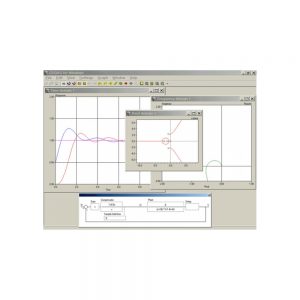
WinCODAS is an application for Control System Design using a Multiple Document Interface (MDI) which allows an arbitrary number of child windows to be created. In each child window the behaviour of a system may be examined in different ways. WinCODAS allows time and frequency responses to be drawn. There is a root domain where root-loci may be plotted either in the s-plane or z-plane.
Nonlinearities may be defined in a flexible and simple manner and their characteristics drawn. These nonlinearities can then be included into the control loop simulation. Time domain responses may be drawn as phase-plane diagrams. A wide range of cost-functions may be defined, settling time, integral of error squared. The cost-functions are evaluated automatically when a response is produced. The frequency domain supports direct and inverse Nyquist diagrams, Bode gain and phase plots and Nichols plots. Closed-loop gain contours (M-contours) may also be drawn. The root domain shows the open-loop poles and zeros of the system and draws root-loci for continuous-time systems with or without transport delay and discrete-time systems. Damping-ratio or Jury contours may be superimposed on a root locus diagram. For rational transfer functions, the positions of all the closed-loop poles may be displayed in a table and marked on the root locus plot.
A digitised cursor is available in all domains to obtain details of data on any plot. The cursor can be switched from absolute to relative mode to allow relative measurements such as peak overshoots or the period of an oscillatory response. There is an auto-scale function and a zoom feature that allows users to magnify any section of a plot. Each child window can have multiple plots; none of which are lost when the window is resized. The system transfer functions are entered in “free-format”. Continuous-time, discrete time and sampled-data systems may be simulated by defining the appropriate transfer function and sample hold time. There are several mapping tools that allow the user to transform transfer functions into explicit z-domain representations including: zero-order hold z-transform, rectangular rule, Tustin’s rule with pre-warping and there are a number of manipulation tools for changing the presentation of the transfer functions into Bode form, pole/zero form. The simulated system is shown graphically in a separate window and its configuration can be different for each child window. As a child window is brought into focus, the system graphic changes dynamically and so the user knows the precise nature of the system being simulated. The general system includes an overall system gain, two transfer functions, a transport delay, two nonlinearities and a zero-order hold. These elements can be included or excluded. There are three possible inputs to the system. In this way the regulation behaviour due to load disturbances and measurement noise can be simulated as well as the performance with more standard set-point or reference inputs.
Key Features
- Free-format transfer functions
- Compensator, Plant
- Transport delay
- Two nonlinearities
- Continuous Time, Sample-data, Discrete time
- Expression evaluator
- Global parameters
- Dynamic system definition schematic
- Measurement noise, Load disturbances
- Transfer-function manipulation tools
(0 reviews)