Air Flow
Showing 19–24 of 24 results
-
 Air Flow and Thermodynamics
Single Stage Air Compressor Test Set – Air Cooled
The test set is for studying the single stage reciprocating air compressor characteristics.
An industrial type compressor is driven via a vee-belt by a motor with an advanced inverter. The air receiver has, safety valves, pressure switch, a drain valve and a discharge valve. The unit is equipped with necessary measuring instruments and is on wheels.
Instruction manual is also included.
TYPICAL EXPERIMENTS- Compressor characteristics e.g. volumetric efficiency, isothermal efficiency, pressure ratio, temperature ratio.
- Effect of compressor speed.
TECHNICAL DATACompressors: – Type Air-cooled, single stage – Displacement 300 ml or approximate equal – Maximum working pressure 8 kg/cm2 Air receiver Approx. 90 L or as requested Measuring instruments – Pressure Pressure gauge at compressor outlet – Air flow rate Inlet orifice plate with air box and inclined water manometer 0-450 mm x 1 mm graduation, multiple slope 1:10, 1:5, 1:2 and 1:1 – Motor input power Advanced inverter – Sensors with digital display - Speed for compressor
- Temperatures for ambient and outlet air
Accessory Barometer Software for data display and analysis by computer (separately supplied). Power supply 220V 1Ph 50 Hz. Other power supply is available on request. (0 reviews) -
 Air Flow and Thermodynamics
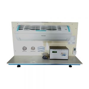
Split Type Air Conditioner System
This unit is used for the demonstration of split type room air conditioning operation. Individual components are clearly shown. Temperatures and pressures at various points are indicated.
Instruction manual is also included.
TYPICAL EXPERIMENTS- Study of layout and process diagram
- Observation of pressures and temperatures
- Remote control operation
TECHNICAL DATACooling capacity Approx. 2.5kW or 9000 BTU Compressor type Rotary Refrigerant R32 Measuring instruments – Pressure gages 2 ea. – Sensors with digital display Temperature for compressor inlet, outlet, condenser outlet, expansion valve outlet and air – side of evaporator inlet and outlet Remote control Required power 1 ea. Software for data display and analysis by computer (separately supplied). Power supply 220 V, 1 Ph, 50Hz. Other power supply is available on request. (0 reviews) -
 Air Flow and Thermodynamics
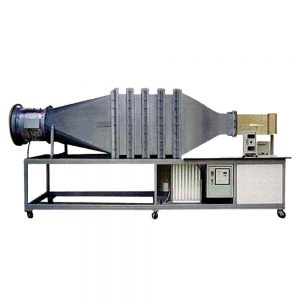
Subsonic Wind Tunnel: Upstream Fan
The wind tunnel is an open circuit upstream fan type, designed for studying the subsonic aerodynamics. It is to be used with optional accessories and models below.
An axial flow fan delivers air through a diffuser, aluminum tube flow straightener, three wire mesh screens and a high contraction ratio section to ensure uniform velocity across the transparent test section. The diffuser and contraction sections have a high quality internal finish to minimize the boundary effects. The fan impeller blades are of an aerofoil design cast aluminum to ensure maximum aerodynamic efficiency and minimum turbulence. The fan speed is adjustable by an inverter.
Four equally spaced static pressure taps are connected to a manifold to minimize effects from a model and air speed is indicated by an inclined manometer and a calibration graph. Models are mounted on two components load cell support with digital display for measurement of drag and lift. Model holder can be rotated to allow quick change on the angle of incidence, this angle is indicated on an angular scale.
The wind tunnel is mounted on a steel table on wheels.
Instruction manual is also included.
TYPICAL EXPERIMENTS- Pressure and velocity measurement.
- Estimation of drag coefficients of various bodies, e.g. sphere, hemisphere, disc, plate, streamlined shape etc.
- Estimation of drag lift and pitching coefficients of an aerofoil.
- Pressure distribution around an aerofoil or a cylinder.
- Effects of instability of a “flutter Wing”.
- Investigation of boundary layer at a flat plate by measuring total head distribution.
- Stream lines visualization using a smoke generator.
- Wakes behind models.
TECHNICAL DATAFan: – Diameter 500 mm – Impeller Single stage, aerofoil aluminum blade Contraction area ratio 7:1 Test Section 300 mm x 300 mm x 600 mm long, transparent on three sides Maximum air velocity Over 30 m/s Measuring instruments – Water manometer Twin type – Wind velocity Contraction section differential pressure with inclined water manometer and velocity calibration graph (to be used with inclined water manometer above) – Sensors with digital display – Lift and drag Two component balance with model holder for measurement of lift and drag Software for data display and analysis by computer (separately supplied). Power supply 220 V, 1 Ph, 50 Hz. Other power supply is available on request. (0 reviews) -
 Air Flow and Thermodynamics
Subsonic Wind Tunnel: Upstream Fan (High Speed)
This subsonic wind tunnel is an open circuit upstream fan type, designed for studying the subsonic aerodynamics. It is to be used with optional accessories and models below.
A dual an axial flow fans delivers air through a diffuser, aluminum tube flow straightener, three wire mesh screens and a high contraction ratio section to ensure uniform velocity across the transparent test section. The diffuser and contraction sections have a high quality internal finish to minimize the boundary effects. The fan impeller blades are of an aerofoil design cast aluminum to ensure maximum aerodynamic efficiency and minimum turbulence. The fan speed is adjustable by an inverter.
Four equally spaced static pressure taps are connected to a manifold to minimize effects from a model and air speed is indicated by an inclined manometer and a calibration graph. Models are mounted on two components load cell support with digital display for measurement of drag and lift. Model holder can be rotated to allow quick change on the angle of incidence, this angle is indicated on an angular scale.
The wind tunnel is mounted on a steel table on wheels.
Instruction manual is also included.
TYPICAL EXPERIMENTS- Pressure and velocity measurement.
- Estimation of drag coefficients of various bodies, e.g. sphere, hemisphere, disc, plate, streamlined shape etc.
- Estimation of drag lift and pitching coefficients of an aerofoil.
- Pressure distribution around an aerofoil or a cylinder.
- Effects of instability of a “flutter Wing”.
- Investigation of boundary layer at a flat plate by measuring total head distribution.
- Stream lines visualization using a smoke generator.
- Wakes behind models.
TECHNICAL DATAFan: – Diameter 630 mm – Impeller Single stage, aerofoil aluminum blade Contraction area ratio 7:1 Test Section 300 mm x 300 mm x 600 mm long, transparent on three sides Maximum air velocity Over 60 m/s Measuring instruments – Water manometer Twin type – Wind velocity Contraction section differential pressure with inclined water manometer and velocity calibration graph (to be used with inclined water manometer above) – Sensors with digital display – Lift and drag Two component balance with model holder for measurement of lift and drag Software for data display and analysis by computer (separately supplied). Power supply 380 V, 3 Ph, 50 Hz. Other power supply is available on request. (0 reviews) -
 Air Flow and Thermodynamics
Two Stage Air Compressor Test Set – Air Cooled
The test set is for studying the two stage reciprocating air compressor characteristics.
An industrial type compressor is driven via a vee-belt by a motor with an advanced inverter. Air cooling between the two stages is by finned tubes. The air receiver has safety valves, pressure switches, a drain valve and a discharge valve. The unit is equipped with necessary measuring instruments and is on wheels.
Instruction manual is also included.
TYPICAL EXPERIMENTS- Compressor characteristics e.g. volumetric efficiency, isothermal efficiency, pressure ratio, temperature ratio.
- Effect of compressor speed.
- Effect of inter cooling (optional).
- Air water heat exchanger demonstration (optional).
TECHNICAL DATACompressors: – Type Air cooled, two stages – Displacement 300 ml or approximately equal – Maximum working pressure 12 kg/cm2 Air receiver Approx. 90 L or as requested Measuring instruments – Pressures Pressure gauges at first stage and second stage outlets – Air flow rate Inlet orifice plate with air box and inclined water manometer, 0-450 mm x 1 mm
graduation, multiple slope 1:10, 1:5, 1:2 and 1:1– Motor input power Advanced inverter – Sensors with digital display - Speed for compressor
- Temperature for ambient and outlet air of each stage
Accessory Barometer Software for data display and analysis by computer (separately supplied). Power supply 220V 1Ph 50 Hz. Other power supply is available on request. (0 reviews) -
 Air Flow and Thermodynamics
Two Stage Air Compressor Test Set: Air-Water Cooled
The test set is for studying the two stage reciprocating air compressor characteristics.
For educational purpose, the two stages are separated and can be operated at different speeds. Both stages are connected by vee-belts to the same motor with an advanced inverter. The second stage compressor has three alternative pulleys to vary the pressure ratio between the two stages. An intercooler is provided between first and second stage. The air receiver has a drain valve, safety valve, pressure switches and a discharge valve. The piping system is arranged such that intercooler or second stage compressor can be by passed. The unit is equipped with necessary measuring instruments and is on wheels.
Instruction manual is also included.
TYPICAL EXPERIMENTS- Compressor characteristics e.g. volumetric efficiency, isothermal efficiency, pressure ratio, temperature ratio.
- Effect of compressor speed.
- Effect of intercooler.
- Effect of second stage drive ratio.
- Effect of inter cooling.
- Air water heat exchanger demonstration.
TECHNICAL DATACompressors: – Type Air-cooled, two stage – Displacement 300 ml. or approximate equal – Second stage Single cylinder, completed with three different diameter pulleys – Maximum working pressure 12 kg/cm2 Air receiver Approx. 90 L or as requested Intercooler Water cooled, counter flow heat exchanger Measuring instruments – Pressures Pressure gauges at first stage and second stage outlets, and air receiver – Air flow rate Inlet orifice plate with air box and inclined water manometer, 0-450 mm x 1 mm
graduation, multiple slope 1:10, 1:5, 1:2 and 1:1– Motor input power Advanced inverter – Sensors with digital display - Speed for compressors
- Temperature for ambient, outlet air of each stage, second stage inlet and cooling water inlet and outlet
Accessory Barometer Software for data display and analysis by computer (separately supplied). Power supply 220V, 1 Ph, 50 Hz. Other power supply is available on request. (0 reviews)


