Skip to navigation
Skip to main content
Home
Engineering Education Products
About us
Blog
Project Documentation
0
Menu
0
0
Mechanical Engineering
Home
»
Mechanical Engineering
Showing 1–12 of 18 results
Sorted by latest
Show sidebar
Show
9
12
18
24
Sort by popularity
Sort by latest
Sort by price: low to high
Sort by price: high to low
Compare
Quick view
Add to wishlist
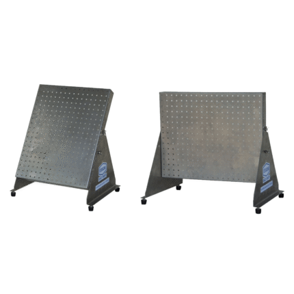
Mechanical Engineering Test Series
Machine Elements and Theory of Machines
Compare
Quick view
Add to wishlist
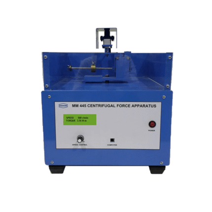
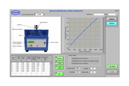
Centrifugal Force Apparatus (Computer Interface)
Machine Elements and Theory of Machines
Compare
Quick view
Add to wishlist
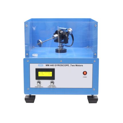
Gyroscope (Two Motors)
Machine Elements and Theory of Machines
Compare
Quick view
Add to wishlist
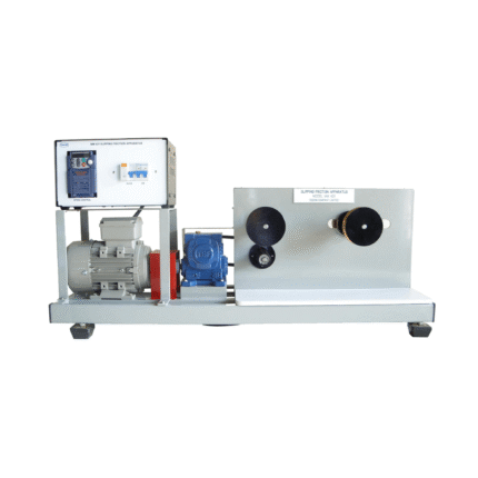
Slipping Friction Apparatus
Machine Elements and Theory of Machines
Compare
Quick view
Add to wishlist
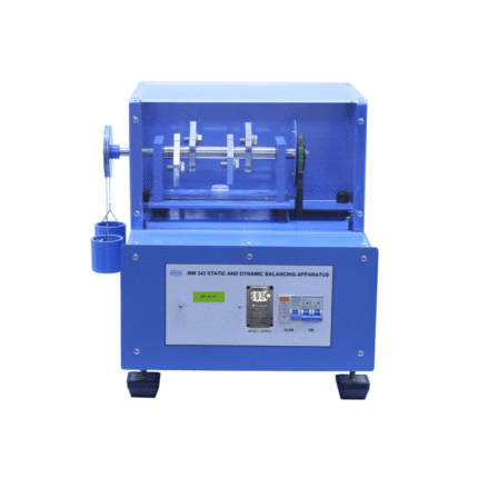
Static and Dynamic Balancing Apparatus
Machine Elements and Theory of Machines
Compare
Quick view
Add to wishlist
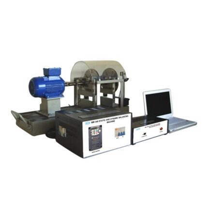
Static and Dynamic Balancing Machine (Computer interface)
Machine Elements and Theory of Machines
Compare
Quick view
Add to wishlist
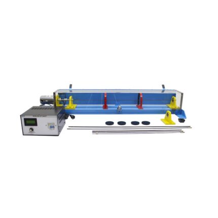
Whirling of Shafts Apparatus
Machine Elements and Theory of Machines
Compare
Quick view
Add to wishlist
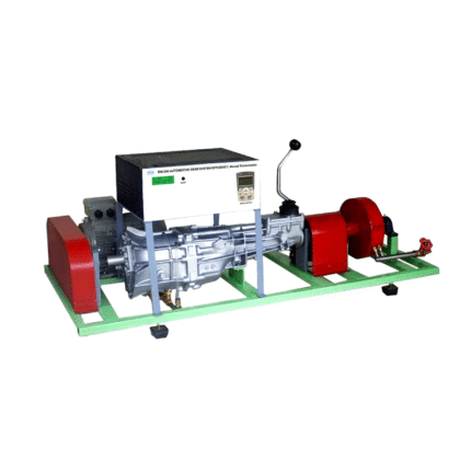
Automotive Gear System Efficiency: Manual Transmission (Computer interface)
Automotive
Compare
Quick view
Add to wishlist
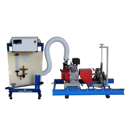
Single Cylinder Engine Test Bed: Mechanical Brake Absorber
Automotive
Compare
Quick view
Add to wishlist
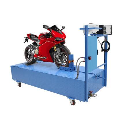
Motor Cycle Dynamometer (Computer Interface)
Automotive
Compare
Quick view
Add to wishlist
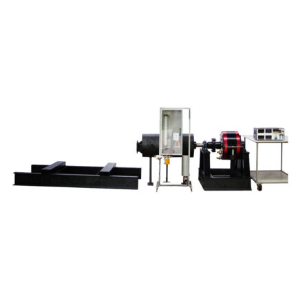
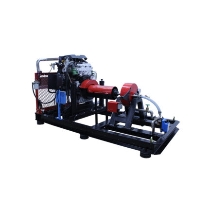
Industrial Diesel Test Bed
Automotive
Compare
Quick view
Add to wishlist
Automotive Engine Test Bed (Computer Control)
Automotive
Search
Start typing to see products you are looking for.
Search
Menu
Categories
Air Flow and Thermodynamics
Energy System & Renewable Energy
Automation
Pneumatics
Automotive
Chemical Engineering & Food Technology
Communications
Electronics, Control System and Instrumentation
Micro Controllers
Fluid Mechanics
Flow Measurement and Flow Study
Hydraulic Studies and Accessories
Pump Test Set
Turbine Test Set
Machine Elements and Theory of Machines
Marine, Naval, Hydrodinamic and Oceanograph
Mechatronics
Miscellaneous Equipment
Peripheral Devices
PLC Trainers
Process Control
Robotic Arms
Strength and Property of Materials
Structures and Accessories
Uncategorized
Home
Engineering Education Products
Blog
Projects
About us
Contact Us
Wishlist
Compare
Login / Register