Skip to navigation
Skip to main content
Home
Engineering Education Products
About us
Blog
Project Documentation
0
Menu
0
0
Hydraulic
Home
»
Hydraulic
Showing all 12 results
Sorted by latest
Show sidebar
Show
9
12
18
24
Sort by popularity
Sort by latest
Sort by price: low to high
Sort by price: high to low
Compare
Quick view
Add to wishlist
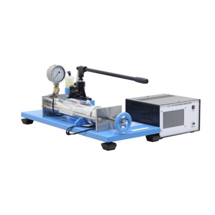
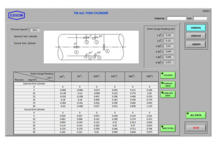
Thin Cylinder
Strength and Property of Materials
Compare
Quick view
Add to wishlist
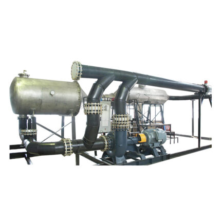
Low Head Hydraulic Turbine Test Rig
Fluid Mechanics
,
Turbine Test Set
Compare
Quick view
Add to wishlist
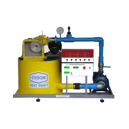
Mini Hydro Power Plant
Fluid Mechanics
,
Turbine Test Set
Compare
Quick view
Add to wishlist
Sediment Flow Channel: 600mm Wide
Flow Measurement and Flow Study
,
Fluid Mechanics
Compare
Quick view
Add to wishlist
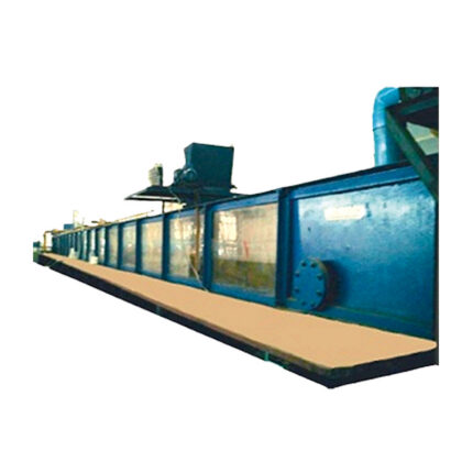
Tilting Flow Channel: 600mm Wide
Flow Measurement and Flow Study
,
Fluid Mechanics
Compare
Quick view
Add to wishlist
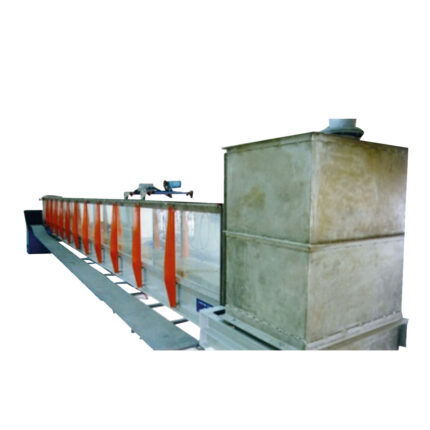
Tilting Flow Channel 300mm Wide
Flow Measurement and Flow Study
,
Fluid Mechanics
Compare
Quick view
Add to wishlist
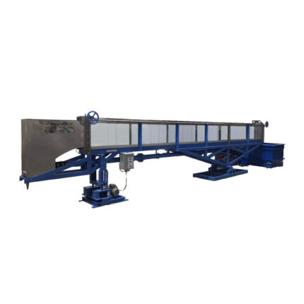
Tilting Flow Channel: 300mm Wide
Flow Measurement and Flow Study
,
Fluid Mechanics
Compare
Quick view
Add to wishlist
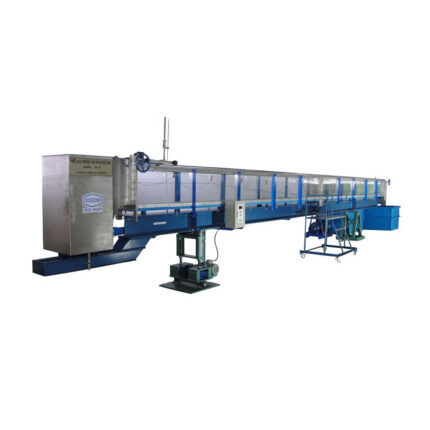
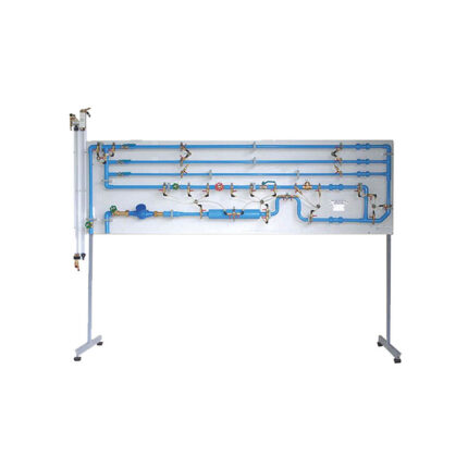
Piping Loss Apparatus (Small)
Flow Measurement and Flow Study
,
Fluid Mechanics
Compare
Quick view
Add to wishlist
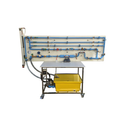
Piping Loss Test Set – Small
Flow Measurement and Flow Study
,
Fluid Mechanics
Compare
Quick view
Add to wishlist
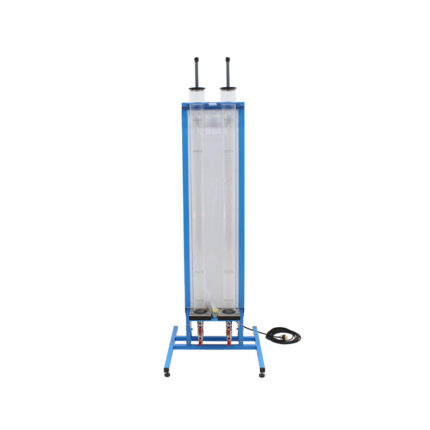
Liquid Sedimentation Apparatus
Flow Measurement and Flow Study
,
Fluid Mechanics
Compare
Quick view
Add to wishlist
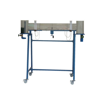
Particle Drag Coefficients
Flow Measurement and Flow Study
,
Fluid Mechanics
Compare
Quick view
Add to wishlist
Open Channel and Closed Channel Flow
Flow Measurement and Flow Study
,
Fluid Mechanics
Search
Start typing to see products you are looking for.
Search
Menu
Categories
Air Flow and Thermodynamics
Energy System & Renewable Energy
Automation
Pneumatics
Automotive
Chemical Engineering & Food Technology
Communications
Electronics, Control System and Instrumentation
Micro Controllers
Fluid Mechanics
Flow Measurement and Flow Study
Hydraulic Studies and Accessories
Pump Test Set
Turbine Test Set
Machine Elements and Theory of Machines
Marine, Naval, Hydrodinamic and Oceanograph
Mechatronics
Miscellaneous Equipment
Peripheral Devices
PLC Trainers
Process Control
Robotic Arms
Strength and Property of Materials
Structures and Accessories
Uncategorized
Home
Engineering Education Products
Blog
Projects
About us
Contact Us
Wishlist
Compare
Login / Register