Skip to navigation
Skip to main content
Home
Engineering Education Products
About us
Blog
Project Documentation
0
Menu
0
0
Air Flow and Thermodynamics
Home
»
Air Flow and Thermodynamics
»
Page 5
Showing 49–60 of 60 results
Sorted by latest
Show sidebar
Show
9
12
18
24
Sort by popularity
Sort by latest
Sort by price: low to high
Sort by price: high to low
Compare
Quick view
Add to wishlist
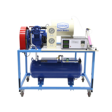
Two Stage Air Compressor Test Set – Air Cooled
Air Flow and Thermodynamics
Compare
Quick view
Add to wishlist
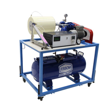
Single Stage Air Compressor Test Set – Air Cooled
Air Flow and Thermodynamics
Compare
Quick view
Add to wishlist
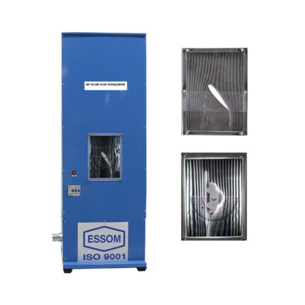
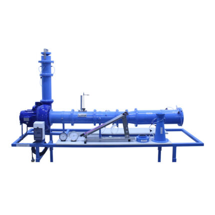
Flow Visualization Wind Tunnel
Air Flow and Thermodynamics
Compare
Quick view
Add to wishlist
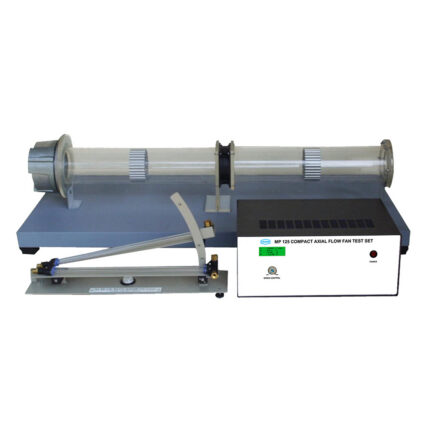
Compact Axial Flow Fan Test Set
Air Flow and Thermodynamics
Compare
Quick view
Add to wishlist
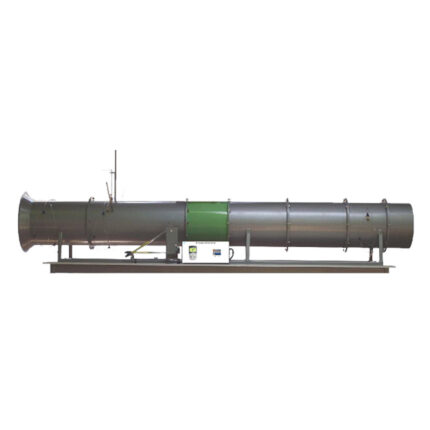
Axial Flow Fan Test Set
Air Flow and Thermodynamics
Compare
Quick view
Add to wishlist
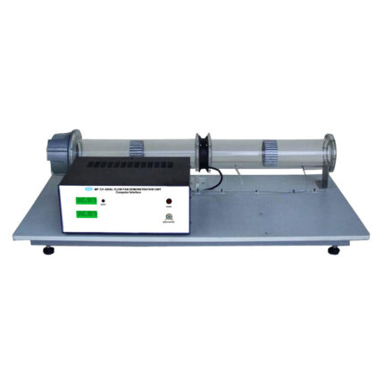
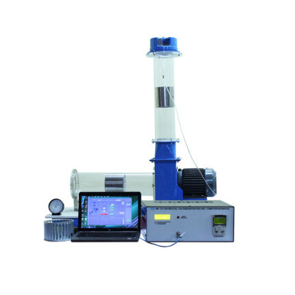
Axial Flow Fan Demonstration Unit (Computer Interface)
Air Flow and Thermodynamics
Compare
Quick view
Add to wishlist
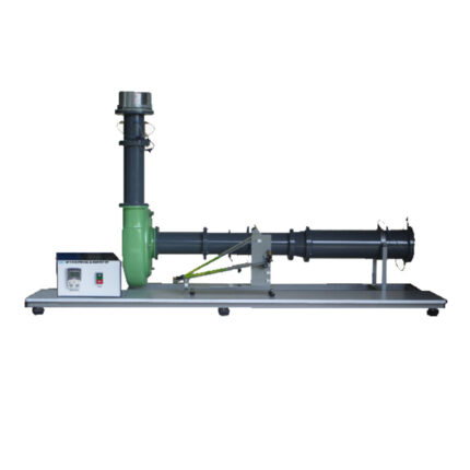
Centrifugal Blower Test Set
Air Flow and Thermodynamics
Compare
Quick view
Add to wishlist
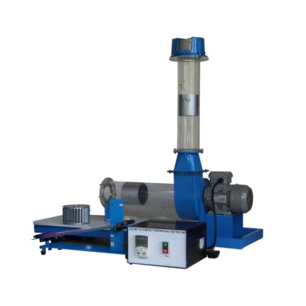
Compact Centrifugal Fan Test Set
Air Flow and Thermodynamics
Compare
Quick view
Add to wishlist
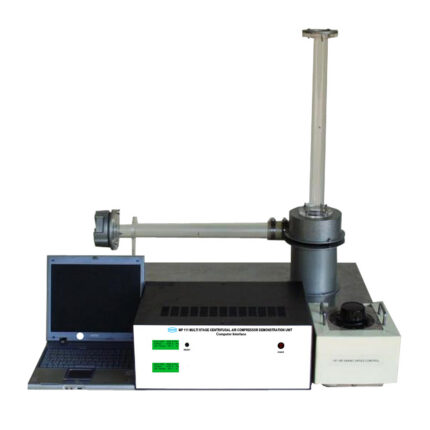
Multi Stage Centrifugal Air Compressor Demonstration Unit (Computer Interface)
Air Flow and Thermodynamics
Compare
Quick view
Add to wishlist
Centrifugal Fan Demonstration Unit (Computer Interface)
Air Flow and Thermodynamics
Compare
Quick view
Add to wishlist
Air Flow Bench
Air Flow and Thermodynamics
Compare
Quick view
Add to wishlist
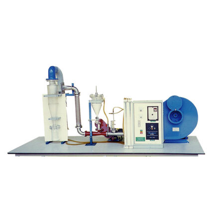
Cyclone Separator
Air Flow and Thermodynamics
Search
Start typing to see products you are looking for.
Search
Menu
Categories
Air Flow and Thermodynamics
Energy System & Renewable Energy
Automation
Pneumatics
Automotive
Chemical Engineering & Food Technology
Communications
Electronics, Control System and Instrumentation
Micro Controllers
Fluid Mechanics
Flow Measurement and Flow Study
Hydraulic Studies and Accessories
Pump Test Set
Turbine Test Set
Machine Elements and Theory of Machines
Marine, Naval, Hydrodinamic and Oceanograph
Mechatronics
Miscellaneous Equipment
Peripheral Devices
PLC Trainers
Process Control
Robotic Arms
Strength and Property of Materials
Structures and Accessories
Uncategorized
Home
Engineering Education Products
Blog
Projects
About us
Contact Us
Wishlist
Compare
Login / Register