Hydraulic Bench
Showing 28–36 of 36 results
-
 Hydraulic Studies and Accessories
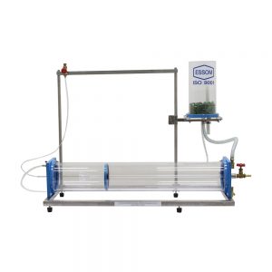
Osborne Reynolds Apparatus: Horizontal Test Pipe
This equipment provides laminar, transitional, and turbulent flow as predicted by Osborne Reynolds. It is to be used with Hydraulics Bench i.e. HB100 or HB100N (separately supplied).
It consists of a removable clear acrylic tank which is partitioned in half. Water is admitted at the bottom of one half through a diffuser and stilling material. The other half of the tank has an adjustable over flow pipe with a discharge at the bottom. Water from the tank is admitted into a clear horizontal shell inside which is a bell entry with a test pipe. Flow through the test pipe is controlled by a discharge valve. A dye injection system needle discharges the dye to the bell mouth and flow pattern in the test pipe can be observed.
TYPICAL EXPERIMENTS- Visualization of laminar, transition and turbulent flow
- Determination of the critical Reynolds number
TECHNICAL DATALength of test pipe 720 mm. Dye reservoir 1 ea. Measuring cup 1 L Software for data display and analysis by computer (separately supplied). (0 reviews) -
 Hydraulic Studies and Accessories
Pipe Friction
This equipment measures pressure drop when water flows through a vertical pipe at various flow rates both laminar and turbulent. It is to be used with Hydraulics Bench i.e. HB100 or HB100N (separately supplied).
It consists of adjustable constant head water source of removable clear acrylic cylinder for laminar flow. Turbulent flow may be achieved by directly connecting the pipe to the Hydraulics Bench water supply. A water manometer with a vent valve, a hand air pump and a differential pressure gauge are provided for measurement of pressure drop. A valve at the outlet is used to control outlet pressure.
TYPICAL EXPERIMENTS- Investigations of laminar and turbulent flows
- Demonstration and measurement in a change of the laws of resistance (friction factor) from laminar to turbulent flow
TECHNICAL DATAWater manometer 450 mm x 1 mm graduation. Differential pressure gauge 1 ea. Test section length Over 500 mm. Measuring cup 1 L. Software for data display and analysis by computer (separately supplied) (0 reviews) -
 Hydraulic Studies and Accessories
Pitot Tube Apparatus
This apparatus is for a study of velocity distribution across pipe section for a water flow in pipe, and for measurement of flow velocity. It is to be used with Hydraulics Bench i.e. HB100 or HB100N (separately supplied).
The apparatus consists of a total head tube and a static head tube for the Pitot, clear acrylic pipe, inlet and outlet, and an inclined manometer. The total head tube can be moved up or down vertically with a scale for indication of the tube position. Differential pressure is measured by a multiple inclination manometer.
TYPICAL EXPERIMENTS- Accuracy of pitot tube meters
- Losses and k value
- Calculation of the coefficient of discharge
TECHNICAL DATAAcrylic tube 34 mm. diameter. Total head probe 1 ea. Inclined water manometer 0-450 x 1 mm graduation. Software for data display and analysis by computer (separately supplied). (0 reviews) -
 Hydraulic Studies and Accessories
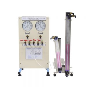
Pressure Measurement Apparatus
The apparatus is intended to introduce students to basic pressure measuring devices as well as pressure gauge calibration.
The apparatus consists of a U-tube and an adjustable inclined water manometers, pressure and vacuum gauges, and a syringe for generation of pressure and vacuum. A dead weight pressure tester is also included.
Instruction manual is also included.
TYPICAL EXPERIMENTS- Familiarization with different pressure measuring devices.
- Comparison of water manometers with pressure and vacuum gauges.
- Comparison of U-tube and inclined water manometers.
- Calibration of pressure gauge.
TECHNICAL DATAPressure gauges, 4 in. 1 ea. vacuum. , 1 ea. pressure. Inclined water manometer 1 ea. U-tube water manometer 1 ea. Syringe HB011 – Dead Weight Pressure Tester
– Pressure
– gauge
– Piston
– cross-section
– Piston
– weights
– Calibration
– weightsSoftware for data display and analysis by computer (separately supplied) (0 reviews) -
 Hydraulic Studies and Accessories
Pump Test Apparatus
This equipment is designed to study of centrifugal pump characteristics at various speed. It is to be used with Hydraulics Bench i.e. HB100 or HB100N (separately supplied).
The pump with motor is mounted on the Hydraulics Bench which acts as a service module. An advanced inverter controls speed as well as indicating speed and input power. Pump hoses with half unions are used to connect the pump with the Hydraulics Bench. Pressure gauges are installed at pump suction with half union and also at pump discharge. The pump draws water from the Hydraulics Bench storage tank via a suction hose with a strainer and delivers flow to the Hydraulics Bench measuring tank (HB100) or flow digital display (HB100N).
TYPICAL EXPERIMENTSPerformance and characteristics of pump
TECHNICAL DATAPump Maximum flow approximately 80 Lpm. Maximum head approximately 18 m. Speed control Advanced inverter. Pressure gauge Suction. Software for data display and analysis by computer (separately supplied). Power supply 220 V, 1 Ph, 50 Hz or as required (0 reviews) -
 Hydraulic Studies and Accessories
Reciprocating Pump
This equipment is designed to study reciprocating pump characteristics at various speeds. It is to be used with Hydraulics Bench i.e. HB100 or HB100N (separately supplied).
The pump and motor are mounted on the Hydraulics Bench which acts as a service module. An advanced inverter controls speed as well as indicating speed and input power. Pressure gauges and pulse chambers are installed at pump suction and discharge. The pump draws water from the Hydraulics Bench storage tank via a suction hose with a strainer and delivers flow to the Hydraulics Bench measuring tank.
TYPICAL EXPERIMENTSPerformance and characteristics of Reciprocating pump
TECHNICAL DATAPump ratings Maximum flow rate approximately 15 Lpm Maximum head approximately 30 m. Pressure gauge Discharge. Software for data display and analysis by computer (separately supplied). Power supply 220 V, 1 Ph, 50 Hz or as required (0 reviews) -
 Mechanics of Fluids
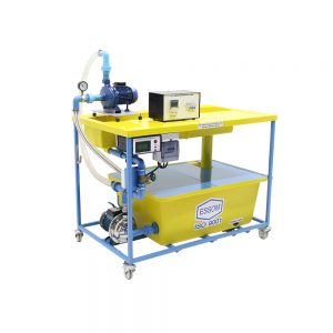
Sediment Bed and Flow Visualization Tank
The equipment is a self-contained unit designed to study the mobile bed formation and two-dimensional flow observation.
The tank is made of stainless steel and consists of five sections.
- Head tank with perforated plate to minimize turbulence and smoothen the flow.
- The working section containing sand is for study of the mobile bed formation and to observe two dimensional flow patterns. Wire mesh is provided to contain the sand. Plastics plates are used when two-dimensional flow is to be observed.
- The storage tank collects discharge from the working section and acts as a reservoir. An adjustable overshot weir is provided to control the water level in the working section. The tank also has a sand trap to collect the over-spilled sand.
- A pump to draw water from the storage tank and deliver it to the head tank. A water meter with a flow control valve are also supplied.
- An instrument carriage traveling on stainless steel tube rails attached to the edges of the working section is designed such that the carriage can travel length wise and crosswise over the working section. A stainless steel vernier hook and point gauge is attached to the carriage to measure the sand profile level.
The first three sections are joined together by flanges and the pump unit is connected to the system by flexible hoses. Various accessories are supplied to simulate different flow obstructions and diversions. An aluminium dust or equal is supplied for two-dimensional flow observations.
Instruction manual is also included.
TYPICAL EXPERIMENTS- Sand bed formation under various flow rates.
- Erosion of sand bed around piers or branch canal.
- Two-dimensional flow pattern around pier and branch canal.
TECHNICAL DATAHead tank Stainless steel Working section Stainless steel, 610 mm wide, 2000 mm long and 150 mm high Storage tank Approx. 300 L, PE Instrument carriage with two direction rails. Hook and point gauge 1 ea. Flow measurement Water meter and stop watch Accessories – Plastic Plates – Bridge piers Rectangles , Rounded ends , Profiled ends , Cylinders – Aerofoil Symmetry , Asymmetry – Sections for flow direction Channels , Tees , Angles , Bell month entries , Channel walls. – Aluminum dust or equal 1 bottle Software for data display and analysis by computer (separately supplied). Power supply 220V, 1 Ph, 50 Hz. Other power supply is available on request. (0 reviews) -
 Hydraulic Studies and Accessories
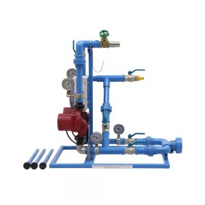
Series and Parallel Pump, Multi Speeds
This equipment is designed to study head vs flow rate characteristics of two pumps connected in series or parallel. It is to be used with Hydraulics Bench i.e. HB100 or HB100N (separately supplied)
It consists of two identical pumps with 3 different speeds, inter connecting pipings, and control valves. Both pumps are interconnected and mounted on a support next to the Hydraulic Bench which acts a service module i.e. water supply and flow measurement. By manipulating flow control valves, the two pumps can be operated individually, or both pumps in series or in parallel. Pressure gauges are installed at pump suction and discharge. The apparatus is equipped with suction hoses and strainers and a discharge hose.
TYPICAL EXPERIMENTSCharacteristics of two pumps connected in series or parallel
TECHNICAL DATAPump Speeds : 3 different speeds. Maximum flow approx. 70 Lpm. Maximum head approx. 7 m water Pressure gauges 4 ea. Software for data display and analysis by computer (separately supplied). Power supply 220 V, 1 Ph, 50 Hz. Other power supply is available on request. (0 reviews) -
 Hydraulic Studies and Accessories
Series and Parallel Pumps, Fixed Speed
This equipment is designed to study head vs flow rate characteristics of two pumps connected in series or parallel. It is to be used with HB100 Hydraulics Bench (separately supplied)
A fixed speed pump is mounted on the Hydraulics Bench which acts as a service module. The Hydraulics Bench pump is used as a second pump. The two pumps are interconnected and by manipulating flow control valves, the pumps can be operated individually or both pumps in series or in parallel. Pressure gauges are installed at the pump suction and discharge. The pump draws water from the Hydraulics Bench storage tank via a suction hose with a strainer and delivers flow to the Hydraulics Bench measuring tank.
TECHNICAL DATAPump ratings : Maximum flow rate 80 lpm and maximum head 18 m. water. Pressure gauges : Suction and discharge. Power supply : 220 V, 1 Ph, 50 Hz. Net (unpacked) shipping dimensions WxLxH : 36 x 90 x 50 cm Net weight : Approx. 18 kg (0 reviews)